Broken Gas Trimmer Handle

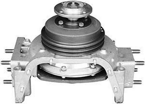
In the trucks of the Kama Automobile Plant, the cooling fan drive is implemented in the form of a special device. a hydraulic coupling located in front of the power unit. Read about how the fluid coupling and its components are arranged and working, as well as its operation, maintenance and repair features, read in this article.
KAMAZ 740 fluid coupling video malfunction
Ural 4320 part 9. Repair of the fluid coupling switch, check of the centrifuge.
KAMAZ fluid coupling animation
Repair and identification of defects of the divider, etc. Kamaz
Why KAMAZ at idle is not heated
Euro Kamaz engine 2 fan clutch diagram
Fluid coupling noise
Engine cooling system. Device and principle of operation
The principle of operation of the planetary fluid coupling
- KAMAZ gearbox presentation
- Chip tuning KAMAZ Cummins
- KAMAZ 6520 brake system accelerator valve
- KAMAZ white swan
- Installation of the thermostat on KAMAZ 740
- KAMAZ trucks with pipes video
- Rubber KAMAZ Euro 43118
- KAMAZ driver attack
- Radiator on KAMAZ 43502
- KAMAZ wipers electric motor characteristics
- Box tent KAMAZ 4308
- Chipper KAMAZ 53215
- KAMAZ rides on the river coub
- KAMAZ 4310 tractor elikon
- Whose spare parts at KAMAZ
Home »Popular» KAMAZ 740 fluid coupling video malfunctions
Stroy-Technika.ru
Construction machinery and equipment, reference book
Checking and adjusting the fluid coupling switch of the Kamaz-740 engine fan drive
Cars Ural-375d, Ural-4320
Checking and adjusting the fluid coupling switch of the Kamaz-740 engine fan drive
Tools and accessories: spanners 14, 17, 19, 22 and 32 mm, 13 mm socket wrench, crowbar for turning the crankshaft, tank for draining the coolant.
Duration of work: 45 min.
Work content and technical specifications Checking the fluid coupling switch
Видео: Broken Gas Trimmer Handle
The fluid coupling switch is checked by turning on the fan in each of its three modes.
Auto mode
1. Set the switch tap to position “B”, for which put the switch rod in its highest position.
2. Start the engine. The fan should automatically turn on at a temperature of 90 ° C and turn off at a temperature of 85 ° C, thereby maintaining the temperature of the coolant within the required limits.
3. Adjust the stroke of the thermosensor switch of the fluid coupling switch in case the temperature of the coolant increases (when the fan is in automatic mode) more than 105 ° C.
Fan off
1. Set the switch tap to the “0” position, for which put the switch rod 2 in the middle position.
2. Start the engine. The fan should not turn on. Its rotation with a small frequency is allowed.
The fan is always on.
1. Set the switch tap to the “P” position, for which put the switch rod 2 in the lowermost position.
2. Start the engine. Regardless of the coolant temperature, the fan is always on.
Hydraulic clutch switch adjustment
1. Drain the coolant from the cooling system.
2. Loosen the nuts and remove the centrifugal oil filter cap and poTopat cap
3. To weaken a lock-nut and a nut of the lever of fastening of the tension device of driving couplings of a hydraulic coupling.
4. To turn away bolts of a directing bar of draft of the switch of a hydraulic coupling, to remove a level and draft.
5. To turn away bolts of the case of the switch and to remove the switch of a hydraulic coupling from the engine.
6. Fasten the fluid coupling switch in a vice, unscrew the nut 15 for fastening the thermo-power sensor and remove the sensor 16 from the housing
7. To adjust the stroke of the spool of the fluid coupling switch. When the fan is turned on late in the automatic operation mode, it is necessary to remove one or more adjusting washers 14 located between the sensor and the switch housing. When turning on the fan early, the number of washers must be added.
8. Tighten the nut of fastening of the thermopower sensor with the moment of 2-2.5 kgf-m.
9. Install the fluid clutch switch to the engine and secure it.
10. Install the switch rod with the guide bar and fasten it with bolts.
11. Adjust the tension of the fluid coupling drive belts in accordance with flow chart No. 21.
12. Install and tighten the nuts of the rotor caps and the centrifugal oil filter.
13. Pour coolant into the system.
14. Start the engine and check the operation of the fluid coupling switch.
Fig. 1. Switch hydraulic coupling of the KamAZ-740 engine:
1. switch housing cover; 2 — thrust; 3. switch housing; 4. a washer of a return spring; 5. a return spring; 6. spool of the fluid coupling switch; 7. a sealing ring of the housing cover; S. sealing ring of the valve plug; 9. plug valve; 10. tap plug lever; 11. spring retainer; 12. lever lock valve plug; 13. valve plug cap; 14. adjusting washers; 15. a nut of fastening of the thermal sensor; 16. thermal power sensor assembly; 17. a sealing ring of the thermopower sensor
Advertising:
Read more: Checking and adjusting the tension of the drive belts
TOCategory:. Cars Ural-375d, Ural-4320