Speed controller with power maintenance for angle grinders
DIY! Speed controller for angle grinder with your own hands
angle grinder, or angle grinder (angle grinder) as it is officially called, sometimes contains a built-in speed regulator. Some models do not have it. Speed control in such a tool is not just a matter of convenience, but often a necessity. Different materials require different cutting or grinding speed, and if the machine does not provide it, at least the quality of work is seriously reduced.
Collector motors with series excitation are used in angle grinders with speed control. They can operate on DC or AC power. This type of motor is easily regulated by changing the current in the circuit.
Because modern regulators use pulse-controlled commands, they do not get very hot and can be built into even small tools. control using a potentiometer whose knob is located on the handle of the machine.
Why control the speed of the blade?
Different cutting or grinding speeds are required depending on the physical properties of the material to be sanded. For example, high speed with low pressure is required when cutting hard materials that might otherwise crumble or split. Soft materials not resistant to heat (thermoplastics, wood), on the contrary, require low speed:
- ceramic: 10,000 rpm;
- metal: 8000 rpm;
- hard plastics: 5000. 8000 rpm;
- wood: 3000. 5000 rpm;
- Soft plastics: less than 2000 rpm.
All professional tools are equipped with a stabilized speed regulator, but inexpensive household angle grinders, power under 1200 watts, are not always supplemented with it. In this article we will talk about how to make such a regulator by ourselves to reduce the speed.
How to build a control circuit?
The traditional speed control circuit is pretty simple: pulse-phase unlocking of a triac, with only a few parts. However, it is not very stable, so a professional tool uses this principle in a more complicated version, with feedback and overcurrent protection (U2008B and U2010B chips).
Now there are more advanced variants, using PWM regulators. Their circuits are a little more complicated, but the main difficulties there arise in setting up and assembling. You may need instrumentation (oscilloscope), and the ability to work with expensive parts that are afraid of static charges. In general, it is not for ordinary consumers.
So it’s better to take an average solution: variant with triac and U2008 chip, this circuit requires only a proper assembling and inexpensive parts. It’s a simple device, but for a household tool it works just fine.
Schematic diagram
The circuit diagram is shown in the figure below:
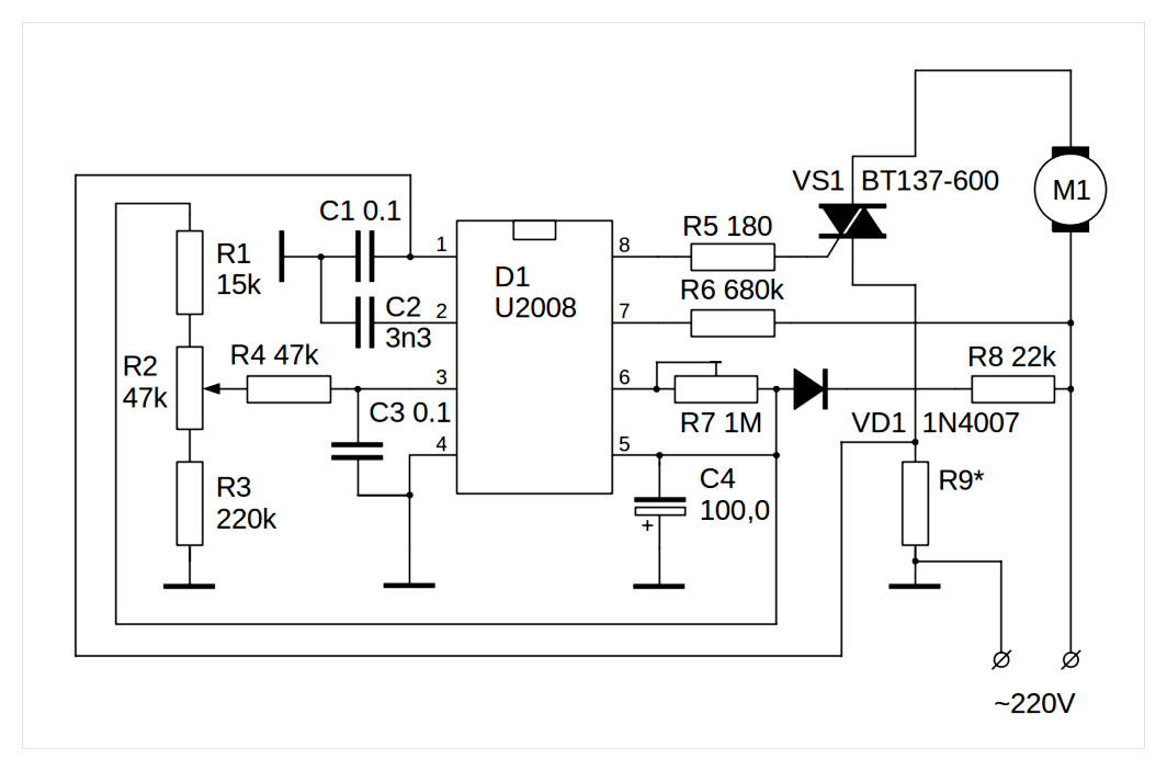
Most of the parts used in the circuit: MLT-0 resistors.25, capacitors K73-17.
WARNING! Resistor R2, regardless of its design, must have a well insulated knob. It has a direct connection to the mains.
Capacitor C4 type K50-35 for 50 V. Note that pin 5 of the D1 chip is negative. The common wire is usually the minus wire, but here it is plus. R5 resistor MLT-0.5, R7 is better to use a multi-turn film resistor. The diode D1 can be KD105B, V or similar. Resistor R8 is MLT-2, it will have a noticeable power drop. The resistor R9 is discussed later.
Circuit operation
The U2008B chip is a voltage stabilized phase regulator. It has a choice between soft start function and speed stabilization. On pin 1 is fed a signal from the current sensor or, if using a soft starter, connect an electrolytic capacitor with a capacity of several microfarads.
You connect the phase shifting capacitor to pin 2. Output 3 is the input of the triac opening angle regulator. The bigger the angle, the later the triac opens in each half cycle, and the less power is delivered to the controlled load. Pin 4 is the common ground for the circuit. Not to be confused with physical ground or ground. Pin 5 is the power supply of the microcircuit, from the rectifier on the resistance R8, diode D1 and capacitor C4.
Pin 6 is the adjustment of the minimum opening angle of the triac. It is adjusted so that at the extreme position of resistor R2 in the load the highest power is achieved. Pin 7 is the line voltage sensor input. The chip uses it to compensate for phase shift and determine the auto-restart level. Also, internally in the chip itself is organized by the current protection in the load.
Pin 8 is the output of the triac control pulses.
Resistor R9 is chosen so that the voltage across it is. 250mV. For this you need to know the current flowing through the motor. It can be determined from the power by dividing the power by the line voltage. For example, for a power of 600 W, the current would be 600/220 = 2.72 А. Then R9 = 0.25/2.72 = 0.09. Resistor 0.1 Ohm can be made from a piece of nichrome wire thick enough so that it does not get hot.
The above circuit will stabilize the speed of rotation, making it independent not only of the mains voltage, but also to a good extent from the load on the angle grinder’s disc. If you only need the soft start you need a jumper instead of R9, and C1 must be replaced with a 22 100 mF electrolytic capacitor. To pin 1 of the microcircuit it is necessary to connect the minus of the capacitor.
Assembly procedure
For the assembly it is best to use printed circuit boards. It will hold the parts firmly. The diagram above is drawn so that it can tell you how to place the parts. all the pins of the chip go from the key in a circle in ascending order. Because of the need to cool the triac, the size of the board can not be less than a matchbox.
It is necessary to cool the triac, because in more or less powerful models of angle grinder about 10-15 W of power will drop on it. So you need to make room for an aluminum heat sink for the triac. Draw the wiring diagram on a life-size sheet of paper and use the puncher to transfer the holes for the connection pins to the workpiece of foilized textolite. The holes are drilled with a mini drill with drill bits of the appropriate diameter for the pins of the parts.
Then, on the side opposite the installation of parts, they carefully draw the tracks with nitrolac, taking care that they do not overlap each other. After the board dries, pickle with a solution of ferric chloride or copper sulfate with ordinary kitchen salt. The etched board should be washed thoroughly with plenty of water and dried. The dried board is brazed using rosin and solder.
You also tin the pins before soldering, taking care not to overheat the semiconductor components, especially the IC. Before tinning you can wipe the leads with alcohol, this can greatly help the quality of tinning, especially if the leads were touched with your hands.
TIP: In jobs like chemistry, tinning, and soldering, a person’s hands are always dirty by definition. The slightest trace of fat will tear the tinning surface and make it hard for the flux to work. Do not touch the tinning surfaces with your hands, use tweezers.
How to connect a device to an angle grinder, options
Connection of the regulator depends on what kind of device is chosen. If a simple circuit is used, it is sufficient to mount it in the power supply channel of the power tool.
Installing a homemade board
There are no ready-made recipes for installation. Everyone who decides to equip an angle grinder with a regulator has it according to their purpose and the model of the tool. Someone inserts the device into the handle of the holder, someone in a special additional box on the body.
In different models, the space inside the body of the angle grinder may be different. In some models, there is enough space for the installation of the control unit. In others, it has to be surface mounted and fastened in some other way. But the trick is that, as a rule, there is always a certain cavity in the back of the tool. It is designed for air circulation and cooling.
This is usually where the factory speed controller is located. The handmade circuit can be placed in this space. To prevent the regulator from burning out, the thyristors must be mounted on a heatsink.
Features of the installation of the finished unit
When buying and installing the factory regulator inside the angle grinder, most often you have to modify the housing. to cut a hole in it for the output of the regulating wheel. But this can have an adverse effect on the rigidity of the housing. Outside installation is therefore preferred.
The speed is changed by the thumbwheel
The numbers on the adjustment wheel indicate the number of spindle revolutions. This value is not absolute, but conditional. “1”. minimum revolutions, “9”. maximum revolutions. Other figures are for orientation during adjustment. The position of the thumb wheel on the housing can be different. For example, on the Bosch PWS 1300-125 CE angle grinder, the Wortex AG 1213-1 E or the Watt WWS-900, it is located at the base of the handle. Other models like the Makita 9565 CVL have the thumbwheel in the end of the housing.
The connection diagram of the regulator to the angle grinder is not complicated, but sometimes it is not so easy to pull cables to the button, which is located at the other end of the device housing. The problem can be solved by selecting the optimum cross section of the wire or bringing it to the surface of the housing.
A good option is to install the regulator on the surface of the device or attach it to the mains cable. Not always everything works on the first try, sometimes the device has to be tested, and then make some adjustments. And this is easier to do when you have access to its elements.
Important! If there is no experience with electrical circuits, it is advisable to buy a ready-made factory regulator or angle grinder, equipped with this function.
Why angle grinder soft start and speed regulator?
In modern angle grinders use 2 necessary options that increase the characteristics and safety of the equipment:
- speed regulator (frequency converter). a device designed to convert the number of revolutions of the motor in different modes of operation;
- soft starter. a circuit that ensures the unhurried build-up of motor speeds from zero to the limit when the unit is connected.
They are used in electromechanical equipment, in the structure of which an alternating current electric motor with a collector is practiced. Help reduce wear and tear of mechanical parts of the engine when switching on. Reduce stress on the electrical components of the machine by enabling them to operate smoothly. As studies of material properties have shown, especially the strongest wear of contacting parts occurs during the sudden transition from a stationary state to a fast activity. For example, one start-up of an internal combustion engine in a car equals the wear of the piston and the group of sealing rings to 700 kilometers of run.
When electric power is on, there is a stepwise transition from a stationary state to lap rotation at the rate of 2.5-10.000 rpm in 60 seconds. anyone who has used an angle grinder knows very well the feeling of the tool “flying out of their hands. It is at this moment that most accidents involving mechanical equipment happen.
The rotor and stator windings feel the same strain. The AC motor with a collector starts in the short-circuit mode, the EMF is already pushing the shaft forward, but the force of inertia does not yet allow it to spin. Starting electric current surge in the motor coils occurs. Although they are designed for this kind of work, there are times (e.g. voltage fluctuations in the mains) when the insulator of the winding cannot cope and a short circuit occurs between the windings.
When introducing the instrumentation schemes of soft start and change of frequency of rotation of the motor into the circuit diagram all the above mentioned troubles disappear spontaneously. In addition the sudden and significant voltage drop in the mains during the start-up of the tool is solved. It is clear from this that household appliances will not be at risk of failure. Circuit breakers on the electric meter will not trip and turn off the current in the apartment or house.
The scheme of soft start is used in middle and high price segment angle grinders, the knot of speed control. more and more in professional modifications of angle grinders. Speed control makes it possible to process soft materials with the angle grinder, to carry out delicate grinding and polishing, because at higher speeds wood or paint will simply burn off. Auxiliary circuitry raises the price of the tool but extends the life and safety of the tool.
The simplest regulator scheme
Electrical diagram of the speed regulator for angle grinder is gathered on a circuit board or hinged mounting. The printed circuit board can also be made by yourself using textolite and bleach for etching. A mixture of hydrogen peroxide, salt and citric acid can be used instead of iron.
Schematic diagram of the motor speed regulator for angle grinder
Circuit configuration
- resistor R1 (4,7 kOhm);
- DIAC symmetrical thyristor (DB3)
- symmetrical thyristor TRIAC (VT-136/138);
- VR1 trimmer resistor (500kOhm);
- Capacitor C1 (0.1 uF400V).
Working principle
The principle of the circuit is as follows. VR1 is responsible for the charging time C1. Thyristors are closed when voltage is applied to the circuit, on the output. 0. As the capacitor is charging, the voltage in the capacitor increases and opens the DIAC, which gives the voltage to the TRIAC. It also opens and passes current. Both thyristors then close and stay in this position until C1 is fully recharged. As a result, the output produces a complex waveform with an amplitude directly depending on the operating time of the C1-VR1-R1 circuit.
Speed regulator connection diagram
Finished assembling and testing the regulator
On a printed circuit board or a copper (aluminum) heatsink is assembled. At the hinged assembly is especially important place of thyristors installation (strictly on the radiator, it plays the role of heat sink). Then there is an obligatory check of the serviceability of the circuit with an ordinary light bulb. The smoothness of change of incandescence will be the same as in the ready-made speed controller for angle grinder after final assembly.
The factory models include a plastic thumbwheel, if you want it can also be bought separately and included in a kit of homemade regulator. If the test was successful, the regulator is mounted on the angle grinder and cut into the power circuit of the tool.
Smooth start of the electric motor of angle grinder with your own hands
Everyone who uses the angle grinder for more than one year, it breaks. At first, every craftsman tried to repair the sparkling grinder himself, hoping that it will work after replacing the brushes. Usually after such an attempt, the broken tool is left lying on the shelf with burned-out windings. And you buy a new angle grinder to replace it.
Drills, screwdrivers, peorators, routers are mandatorily equipped with a speed regulator. Some so-called calibration grinders are also equipped with a regulator, and the usual angle grinder has only a button.
Low-power angle grinder manufacturers do not intentionally complicate with additional circuits, because such power tools should cost cheap. It is clear, of course, that the life of an inexpensive tool is always shorter than that of a more expensive professional.
The most simple angle grinder can be upgraded, so that the gearbox and armature winding wires will no longer be damaged. These troubles mostly occur with a sharp, in other words, percussive start of the angle grinder.
The only thing you need to do is to assemble the electronic circuit and fix it in the box. In a separate box, because there is very little space in the handle of the grinder.
Tested, working circuit is given below. It was originally designed for the adjustment of filament lamps, i.e., to work with an active load. Its main advantage ? Simplicity.
- The highlight of the device soft starter, circuit diagram which you see, is a chip K1182PM1R. This chip is a highly specialized, domestically made.
- The acceleration time can be increased by selecting a higher capacity capacitor C3. While charging this capacitor, the electric motor reaches its maximum speed.
- There is no need to replace the resistor R1 with a variable resistor. Resistor of 68 kOhm is optimal for this circuit. With this setting you can smoothly run an angle grinder of power from 600 to 1500 watts.
- If you are going to build a power regulator, then you must replace the resistor R1 with a variable resistor. Resistance of 100k ohms or more doesn’t make the output voltage too low. By short-circuiting the pins of the chip, you can turn off the connected angle grinder at all.
- By inserting in the power circuit a sevenistor VS1 type TC-122-25, i.e. 25A, you can smoothly run almost any commercially available grinder, power from 600 to 2700 W. And there’s plenty of power left over in case the grinder jams. For connection of angle grinders with power up to 1500 W, imported semistors BT139, BT140 are enough. These less powerful electronic wrenches are cheaper.
The triac in the above circuit is not fully open, it cuts off about 15V of line voltage. This voltage drop has no effect on the angle grinder. But if the semistors get hot, the speed of the connected tool is greatly reduced. This problem can be solved by installing a heat sink.
This simple circuit has another disadvantage. it is incompatible with the speed regulator installed in the tool.
The assembled circuit must be hidden in a plastic box. The insulating material housing is important, because you need to protect yourself from line voltage. You can buy a junction box in a store for electrical appliances.
Screwed to the box is a socket and plug cable with plug, which makes this design looks like an extension cord.
If you have experience and wish, you can assemble a more complex soft starter circuit. The following circuit diagram is the standard diagram for the XS-12 module. This module is factory installed in power tools.
If you need to change the speed of the connected electric motor, then the scheme is more complicated: a 100 kOhm trimmer and a 50 kOhm resistor are installed. Or it is possible to simply and roughly implement a 470 kOhm variable between the 47 kOhm resistor and the diode.
It is desirable to connect a resistor of 1 megohm in parallel to the capacitor C2 (it is not shown in the diagram below).
The LM358 supply voltage is between 5V and 35V. The power supply voltage is less than 25V. Therefore, you can do without the additional DZ stabilizer.
Whatever soft starter circuit you have assembled, never run the tool under load. Any soft starter can be burned if you hurry. Wait for the angle grinder to spin up, and then work.
Diagram of a soft starter motor angle grinder with his own hands
Everyone who has been using an angle grinder for more than a year has had it break. At first, every handyman tried to repair a sparkling sander by himself, hoping it would work after replacing the brushes. Usually after such an attempt, the broken tool is left lying on the shelf with burned-out windings. And you buy a new angle grinder to replace it.
Drills, screwdrivers, torches, routers are necessarily equipped with a speed regulator. Some so-called calibration grinders are also equipped with a regulator, while ordinary angle grinders only have a button.
Low-power angle grinder manufacturers do not deliberately complicate with additional circuits, because such power tools should cost cheap. It is clear, of course, that the life of an inexpensive tool is always shorter than that of a more expensive professional one.
The simplest angle grinder can be upgraded so that its gearbox and armature winding wires stop getting damaged. These problems mostly occur with a sharp, in other words, percussive start angle grinder.
All modernization consists only in assembling the electronic circuit and fixing it in the box. In a separate box because there is very little space in the handle of the grinder.
A proven, working circuit is laid out below. It was originally designed to regulate the incandescence of lamps, that is, to work on an active load. Its main advantage ? simplicity.
- The highlight of the soft starter, the circuit diagram of which you can see, is the K1182PM1R chip. This circuit is a highly specialized, domestically made.
- The acceleration time can be increased by choosing a higher capacitor C3. While charging this capacitor, the electric motor reaches its maximum speed.
- No need to replace resistor R1 with a variable resistor. A resistor of 68 kOhm is optimal for this circuit. With this setting you can smoothly start the angle grinder with a power of 600 to 1500 watts.
- If you are going to build a power regulator, then you need to replace the resistor R1 with a variable resistance. Resistance of 100 kOhm or more does not decrease the output voltage. By short-circuiting the pins of the chip, you can turn off the connected angle grinder at all.
- Having inserted in the power circuit a sevenistor VS1 type TC-122-25, i.e. 25A, you can smoothly start almost any commercially available grinder, power from 600 to 2700 W. And there is a large power reserve in case of grinder jamming. For connection of angle grinders with power up to 1500 W, imported semistors BT139, BT140 are enough. These less powerful electronic wrenches are cheaper.
The triac in the above circuit is not fully open, it cuts off about 15V of line voltage. Such a voltage drop does not affect the operation of the angle grinder. But when the semistors get hot, the RPM of the connected tool is greatly reduced. This problem is solved by installing a heat sink.
This simple circuit has another disadvantage: it is incompatible with the RPM regulator installed in the tool.
The assembled circuit should be hidden in a plastic box. The insulating enclosure is important, because you need to protect yourself from the line voltage. You can buy a junction box at a hardware store.
A socket is screwed to the box and a cable with a plug is connected, which makes this design look like an extension cord.
If you have the experience and desire, you can assemble a more complex soft starter circuit. The following wiring diagram is the standard diagram for the XS-12 module. This module is factory installed in power tools.
If you need to change the speed of the connected motor, then the scheme is more complicated: you set the trimmer, 100 kOhm, and the regulating resistor of 50 kOhm. Or you can just and roughly put a 470 kOhm variable between the 47 kOhm resistor and the diode.
It is desirable to connect a resistor of 1 megohm in parallel to the capacitor C2 (it is not shown on the schematic below).
The LM358 chip supply voltage ranges from 5V to 35V. Voltage in supply circuit does not exceed 25V. Therefore you can do without the additional DZ diode.
Whatever softstarter you have built, never switch the tool connected to it under load. Any soft start can be burnt out if you start in a hurry. Wait until the angle grinder unwinds, and then work.
Regulator installation on angle grinder
Speed regulator for angle grinder with their own hands can be mounted in four variants:
Regulator installation on angle grinder. schematic diagram
- into the handle;
- into the outer box, which is attached in a convenient place on the body of the tool;
- into the cooling cavity (this is what manufacturers use);
- on the mains cable.
Installing an additional box does not require cutting the housing for the regulator output, but the place should be chosen very carefully, so that the innovation does not interfere with a comfortable hold on the tool. Mounting in the handle or cooling cavity will require cutting a hole for the outlet of the regulating wheel, here the main thing. do not lose the rigidity of the protective cover and well clean the edges, so as not to hurt your hands when working.
Often the best option is to mount it on a wire. In this case, the regulator is easy to test, no need to think about the place and method of attachment (duct tape and plastic housing will do). This can always be removed and rewired if desired.
Circuit operation
VR1 trimmer resistor changes the time of the capacitor C1 charge. When voltage is applied to the circuit, at the 1st instant of time (1st half-period of the input sinusoid) the triacs DB3 and TRIAC are closed. Voltage on the output is zero. Capacitor C1 is being charged, the voltage here increases. At a certain point in time, set by the R1-VR1 circuit, the voltage across the capacitor exceeds the opening threshold of the triac DB3, the triac opens. The voltage from the capacitor is transferred to the TRIAC’s control electrode, which also opens. A current starts flowing through the open triac. At the beginning of the second half-cycle of the sinusoid the triacs close until the capacitor C1 is recharged in the opposite direction. Thus, the output is a pulse signal of a complex shape, the amplitude of which is dependent on the operating time of the circuit C1-VR1-R1.
What is a soft start?
Smooth start of the angle grinder is a stepped voltage supply to its motor at which it accelerates without surges of starting current and with a gradual increase in torque. This mode protects the supply network from excessive power extraction and prevents it from “sagging”. This is especially true when powering the angle grinder from an autonomous voltage source. It also protects the motor windings from excessive currents, which could lead to breakdown. The gearbox of the angle grinder is not subject to shock loads during the soft start, which protects it from premature wear.
The electronic circuitry ensuring the angle grinder’s soft start is based on the same principle as the speed regulator. A triac is also used here to limit the power input to the motor. But unlike the speed regulator, the control pulses to the triac are formed not by manual setting of resistance in the RC-chain, but by the electronic circuit which forms the pulse sequence with decreasing delay time. The diagram below shows how the pulse shift time is reduced and the power supplied to the angle grinder motor increases.
Since the softstarter and speed controller use the same circuitry, electronic units are available that combine the functions of both devices.
What is a soft start
A smooth start of the angle grinder is a growing supply of voltage to its motor at which it accelerates without surges of starting current and with a gradual increase in torque. This mode protects the mains from excessive power takeoff and prevents the mains from “sagging. This is especially true when powering the angle grinder from an off-line voltage source. It also protects the motor windings from excessive currents that could cause a breakdown. With a soft start, the gearbox of the angle grinder does not experience shock loads, which protects it from premature wear.
The electronic circuit for the soft start of the angle grinder is based on the same principle as the speed regulator. A triac is also used here to limit the power to the motor. But unlike speed controller the control pulses to the triac are formed not by manual setting of resistance in the RC-chain, but by the electronic circuit which forms the pulse sequence with decreasing delay time. The diagram below shows how the pulse shift time is reduced and the power supplied to the angle grinder motor increases.
Since the soft starter and speed controller operate on the same circuitry, electronic units are available that combine the functions of both.
Installation of a homemade circuit board
Unacceptable off-the-shelf installation recipes. Those who have decided to equip an angle grinder regulator, have it according to their goals model of the tool. Some people put the device in the holder handle, and some in a special additional box on the housing.
In different models, the place inside the body of the angle grinder and possibly different. In some quite free space for the installation of the control unit. In others, you have to take it to the surface and strengthen it with another method. But the trick is the fact that, usually, in the back of the tool, there is always a certain cavity. It is designed for air circulation and cooling.
This is usually where the factory speed regulator is placed. The home-built circuit is of course to put in this place. What the regulator does not burn out, thyristors should be installed on a radiator.
Regulator speed for the angle grinder with their own hands
Although the creation of the speed regulator for angle grinder few, who is necessary, there are still models that have made manual adjustment of disk speed. Adjusting an angle grinder is much different than an electric electric screwdriver or drill because:
- A completely different grip is used throughout the operation.
- It is not permitted to make adjustments during operation. Adjustment should only be carried out with the machine turned off.
The speed of the disc must be adjusted
- When cutting metal (regardless of the thickness of the material), the result of the work carried out depends on the speed of the disc. If you are cutting thicker material the speed should be as fast as possible. If you are working with a material that is not very thick, then the speed must be reduced because a high speed would quickly wash out the disc surface.
- Danger exists if tiles are cut at high speed. Also the disc, rotating at high speed, starts to chop off small pieces of material and so makes the surface roughened. Since the stone has a variety of types, a certain speed is used for each type. For many minerals, high RPMs are used.
- If grinding or polishing is carried out, the adjustment of the speed of the angle grinder is simply necessary. If the speed is set incorrectly, the surface of the material will be damaged. For example, material that has a paint coating may be ruined.
- If you constantly use discs that have different diameters, then the speed controller for the angle grinder must be available. If you change the angle grinder disc to another disc that has a larger diameter, the RPM speed must be reduced. You cannot hold a grinder that has a disc with a huge diameter.
- The choice of speed when polishing concrete material is dependent on the use of a particular type of bits. The torque must not be reduced by reducing the rotational speed.
- If you apply a diamond disk, then the number of its revolutions should be reduced, otherwise the surface due to overheating will begin to fail. Of course, if you use an angle grinder to cut pipes, angles or profiles, then the presence of the regulator is not necessary. But if the angle grinder is used for a variety of purposes, then the RPM regulator for the angle grinder is just necessary. All these reasons show that the presence of a regulator of angle grinder is a must.
Angle grinder regulator description
The angle grinder regulator is a rheostat (variable resistor) that reduces the voltage (all done by the regulator). You need to control the amperage, because if you reduce the number of revolutions will reduce the power of the construction machine. Consequently the torque will be reduced. As a result, it will become a small voltage value, and at a certain resistance the electric motor will not be able to turn the shaft. Therefore, it is necessary to follow a certain scheme: The scheme of the angle grinder is made up of a soft starter module and directly the speed regulator.
Modern advanced models have a distinctive electronic system, and not everyone can afford to buy it.
Independent creation of the regulator
How to make a regulator by yourself? The desire to attach a simple electronic device designed to change the electric power (dimmer) ends up with nothing. First of all, the dimmer for the angle grinder is designed for a different load. Also, the dimmer has no overlap with the control of the electric motor winding. Therefore, you need to install a separate circuit. You also need to think about where it will be located inside the body of the angle grinder.
An important point: if you do not have any experience with electrical circuits, it is best to buy a ready-made brand regulator for angle grinder or angle grinder with the presence of this function.
A simple semiconductor device (thyristor controller) can be constructed with your own hands. For this procedure will need 5 radio elements. Radio elements can be purchased at flea markets. Due to the compactness, you can safely hold the prepared scheme in the angle grinder, without damaging the ergonomics and reliability. However, torque conservation does not occur when the RPMs are reduced on the angle grinder. This option is best for machining soft metals and also tinplate, which has a small thickness.
If you are machining stone, you must install a disc that is 180 millimeters in size. The next step is to create a more complex regulator circuit. In this circuit, the control module will be the chip KR1182PM1. This circuit has control over the amperage at different RPMs, and also makes the loss of torque minimal as RPMs decrease. The operation of the motor is increased with this circuit.
If an angle grinder is used as a circular grinder, the angle grinder must be equipped with a connection point. Thanks to such a point, the connection is made, and the speed can be regulated remotely. You have a great home-built speed controller.
It does not depend on how you made the regulator, it is a mandatory component of the angle grinder, which makes the possibilities of work wider and allows you to comfortably use this construction tool. Also, after installing the regulator, you should do a test run of the angle grinder to see if the construction tool pulls out of your hands. You can make an external speed regulator for the angle grinder with your own hands.
How to assemble an adjustment circuit?
The traditional speed control circuit is quite simple: the phase-pulse unlocking of a triac, it has only a few parts. However, it is not very stable, so professional tools use this principle in a more complicated version, with feedback and overcurrent protection (chips U2008B and U2010B).
Now there are more advanced variants, using PWM controllers. Their circuits are a little more complicated, but the main difficulties arise in setting up and assembling them. You may need an instrument (oscilloscope), and know how to work with expensive parts that are afraid of static charges. In general, this is not for ordinary consumers.
Therefore it is better to take an average solution: a variant with a triac and a U2008 chip, this circuit requires only a correct assembly and inexpensive parts. An uncomplicated device, but for a household tool it works just fine.
Schematic diagram
The circuit diagram is shown in the figure below:
Most of the parts used in the circuit: MLT-0 resistors.25, capacitors K73-17.
WARNING! Resistor R2, regardless of its design, must have a well insulated knob. It has a direct connection to the mains.
Condenser C4 type K50-35 for 50 V. It is necessary to take into account that on pin 5 of chip D1 there is a negative voltage. Usually the common wire in circuits is minus, but here it is plus. Resistor R5 MLT-0.5, R7. better to use a multi-turn film resistor. The diode D1 can be KD105B, V or similar. The resistor R8 is MLT-2, on it will drop a noticeable power. Resistor R9 is discussed later.
Circuit operation
The U2008B chip is a voltage regulated phasor. It has a choice of soft start function and speed stabilization. On pin 1 connects the signal from the current sensor or, if a soft starter is used, connect an electrolytic capacitor with a capacity of several microfarads.
Types of faults of electrical and mechanical parts of the drill
The most common problems with the electrical component are cases where the drill sparks on the brushes due to significant grinding or wear and tear. An appliance with badly worn brushes will not turn on at all. Signs of problems with the engine. no signs of it turning on (sound, vibration, etc.). Reverse and speed control may no longer work in a speed-controlled drill.
Mechanical failures. bearing or gear mechanism failure, shaft failure. They are manifested by hum, intermittent stops of the device, slow rotation. Sometimes there are problems with the chuck: difficulties in disconnecting the drill, unscrewing the chuck relative to the shaft.
Necessary tool
Planning the procedure for repairing the drill with your own hands, you will need to prepare the following tools:
- screwdriver with attachments;
- vise;
- bearing puller;
- nut and socket wrenches;
- an emery for grinding;
- ohmmeter and megger;
- pliers;
- caliper.
In order to competently make your own repair drill, you need to understand the structure of its electrical and mechanical stuffing. In such a case, most faults can be corrected at home.