What kind of turning operation the hook cutter is used for
Cutting tools: types, purpose, geometry, installation methods
At turning various workpieces or parts the following types of cutting tools are used: cutters, drills, countersinks, reamers, taps, dies.
Cutters are the most common type of tool used on lathes for turning internal and external surfaces, parting off workpieces, chamfering and trimming faces, threading. Cutters are made of high-speed tool steel, hard alloys, ceramics and superhard materials (elbor or ismit (a superhard artificial composite material).
High speed steel cutters are used for roughing and finishing of steel on low power machines and at low cutting speeds. Carbide cutters (usually with soldered or mechanically mounted carbide plates) are widely used for roughing and finishing of steel, cast iron, non-ferrous metals and non-metallic materials, they provide work with great depth of cut, feed rates and high cutting speeds. Cutters made by powder metallurgy method from special powder materials are applied for steel finishing turning at low depth of cut, feed rates and low speeds under hammerless load conditions. Cutters equipped with plates of superhard materials (elbor, ismit) are used in finishing and fine diamond turning of workpieces mainly from hardened and alloyed steel.
According to their purpose cutters are subdivided into: cutting, boring, undercutting, feed-through (straight and curved), profiled, grooving, threading. Cutting tools are produced in lengths from 32 to 500 mm, by section of toolholders they are rectangular, square and round, by construction. solid and assembled, soldered and with mechanical attachment of cutting inserts on the body. toolholders.
High-speed steel cutters Р6М5К5, Р6М5, Р9М4К8,10Р8МЗ are most widely spread. Cutting tools Р9М4К8, 10Р8МЗ are used for turning of constructional steels with NHSE hardness 40-45, heat resisting steels and its alloys under conditions of permanent cutting. Cobalt-containing cutters made of Р6М5К5 and Р9М4К8 steel grades are used for lathe machining of workpieces (pieces) made of steel with time resistance over 880 MPa and high-strength modified cast iron.
Cutters made of high-speed steel are produced with three front surfaces:
- 1. Radius with chamfer (except shaped cutters with complex outline of cutting edge). cutters for blanks (details) from steel with providing of chip curl, and their chamfer is executed with width:/=(0,8. 1) S, where S- feed rate, mm/rev. For feedthrough and boring cutters the notch radius L = (10. 15) Y, and for slotting and chamfering cutters R = (50. 60) S, but not less than 3 mm.
- 2. Flat with chamfer. when turning steel workpieces (parts) with feed rate up to 0,2 mm/rev., and it is recommended to round off cutting edges of cutters by blunting them with an abrasive bar.
- 3. Flat without chamfer. when turning steel and iron workpieces with the feed rate of 0,2 mm/rev.
In tab. 5.3 given are the values of the front and main rear corners for HSS cutters of different materials.
Table 5.3. Recommended values for front and main rear corners of high-speed steel cutters, degrees.
Angle of approach with frontal surface form
Carbon, alloyed and tool steels
When machining discontinuous surfaces and castings the rake angle of picks is taken as 20° or 12° instead of the 25° to 30° and 20° given in the table. 5.3. With these cutters a radius of curvature is given r= 1,5 mm for roughing at cutter section 20×30 and 25×40 mm and г = 3 mm for finishing at a cutter section of 25×25 mm and 30×30 mm. Auxiliary rear angle for lead-through, undercutting and boring picks is taken equal to the main rear angle a, for cut-off and parting picks a! = 1-2°, with the larger value а1 is selected for edge widths greater than 5 mm (Fig. 5.2).
Main angle of cutters with feed picks is taken as 30° when turning with a rake angle greater than 25° (under the condition of firm clamping of cutter and workpiece); 45°. when turning lengthwise; 60° to 75° with low rigidity of the technological system; 90° for feed, undercutting and parting-off cutters with simultaneous longitudinal turning and undercutting of non-rigid workpieces like shafts or axles as well as for boring at the stop and small hole diameters. Auxiliary angle in plan view
While cutting workpieces (pieces) on a lathe (universal turning and screw-cutting lathe, automatic lathe, semiautomatic lathe, CNC lathe) a turner uses tables, in which all geometrical parameters of the cutting tools. cutters, drills, countersinks, reamers, etc. are specified.д., including data on the immediate cutting part, which is in contact with the machining surfaces, as well as the rules of sharpening tools.
Cutters equipped with tungsten carbide inserts or mechanically clamped replaceable multifaceted inserts, are widely used in turning, they are called picks. Changeable cutting carbide inserts with screw fastening on tool body (toolholder) are: square, triangular, rhombic, parallelogram, round, and pentahedral. For example, cutters with diamond-shaped interchangeable carbide inserts are used for contour turning on CNC machines, where several surfaces of the workpiece (workpiece) are turned in one working stroke. When equipped with indexable inserts without reverse angle, special superimposed chipbreakers made of hard alloys are used. They are fastened to the toolholder with a clamp and a differential screw, also on the toolholder, while the tools equipped with inserts with reverse angle have chipbreaker grooves on their front surface for chip breaking and drainage of drainage chips. Changeable and non-replaceable carbide inserts are mainly used for tapping, grooving and cutting workpieces. Various cutters with replaceable multifaceted carbide inserts with wedge clamping are used for roughing and finishing of workpieces on universal manual lathes with one cutter. the screw clamps the indexing insert to the stud on which it is clamped to the carrier plate on the tool body (toolholder). It is easy to remove the replaceable carbide. The practice of using such cutters has shown their high reliability and efficiency.
Turning
Lathes are used for turning cylinders, trimming ends, grooving outside the workpiece, cutting moldings to size, expanding holes, drilling, reaming, countersinking, and boring grooves inside the workpiece. On the units the alignment, profile shaping, thread forming with dies, picks, taps, cone processing are performed.
Cutters for various applications
The basic tools are picks, which are subdivided into roughing and finishing variants. Cutter sizes are such that they handle small and large removable areas. Depending on blade shape and location, cutters can be
Straight feedthrough and offset tools are used for turning the outer areas of the workpiece. They act like a boring cutter in the longitudinal feed of the workpiece, and act as a scoring tool in the cross travel. To process the face and the side of a cylindrical body at the same time, thrust feed picks are used, which process the surface in longitudinal feed.
Undercutting picks process the front parts of the workpieces, they are turned by transverse motion of the feed to the central direction or from the center of the workpiece. Boring picks are used to enlarge the diameter of holes already existing in the workpiece. Boring cutters are used in two types of work:
- Borers are used to enlarge the diameter of the hole at an angle of 45° to 62°;
- thrust cutters. increasing the diameter of the blind hole, angle of 90˚.
Cutting picks cut workpieces to size, separate finished parts and create grooves on the outside surface. They start at a cross feed. The main cutting edge is set at a right angle, the two additional cutting edges at an angle of 1 to 3˚.
Shaped tools are used for turning shaped surfaces from an extended line up to a section of 30-45 mm, with the shape of the cutting edge corresponding to the profile. This cutter type is subdivided into round, bar and prismatic. Depending on the direction of movement, they are divided into tangential and radial tools.
Shaped surfaces are processed with rod tools on screw-turning lathes, and cutters of this type are fixed in the toolholder of the unit. Thread cutters are used to form threads inside or outside the workpiece and the thread profile can be trapezoidal, triangular or rectangular. The shape of the cutting edges of such tools corresponds to the size of the cross section and the profile of the thread.
manufacturing methods
Depending on the complexity of production, the tools can be called picks:
- tools made from the whole workpiece;
- composite working tools on the principle of inseparable connection;
- Cutters with soldered-on chucks;
- with mechanical fastening.
Cutting tools are subdivided in left-hand and right-hand cutting tools according to direction of travel. Right-handed tools are distinguished by the fact that the main cutting edge is located (if you put it on top of the cutter) on the right-handed side. Cutting tool moves from right to left, towards the headstock. Left-handed picks have a cutting edge on the left-hand side and move from left to right in the machine.
Handrails are made of structural steel of 40, 40X, 50 and 45 grades, its cross-section may be round, square or rectangular. Fasten the working part to the holder by soldering and mechanical method. The second method is the most reliable, eliminates cracks under load, extends the life of the tool.
The significance of angles in cutting tool design
According to the purpose of work, turner cutters are divided into boring, sinking, profiled, parting, grooving and tapping. For precise operation and high productivity, it is important to determine the geometry of the pick, which depends on the tool angle. This characteristic defines the angle between the cutting edges of the pick and the tool travel direction:
- The main angle in plan depends on the installation of the pick in the machine and the accuracy of the sharpening;
- The additional angle in the plan depends on the same parameters;
- The apex angle is only dependent on the quality of the tool ground.
if the rake angle is small, the major part of the cutting edge comes into play, the heat removal rate increases, and the wear resistance of the pick is greater. A large main angle reduces the length of the working edge and the tool durability is reduced. If the workpiece is long and flexible, a large cutter angle is used which reduces the cutting pressure.
The supplementary (auxiliary) angle is between the auxiliary cutting edge and the line of motion. If it is small, the edge cuts into the honed surface and breaks its integrity. An increased auxiliary angle weakens the pick tip, usually between 10° and 30°.
Multi-faceted cutting inserts
Such tools for a lathe are prepared with up to 4-6 facets. To achieve a positive angle at the front of the plate, chamfers and cavities are created along the edges by pressing, then sintering.
Cam chuck with self-centering function
Various adaptations and devices expand the functionality of the metal-cutting machine and make it versatile. In lathe work these are centers, chucks, lunettes. Drill chucks, collars and various bushings are used to expand the range of operations. The most common is the jaw-type self-centering chuck, whose model has three elements moving simultaneously in a radial direction, so that the workpiece is positioned along the spindle axis.
Other machining attachments:
- if the workpiece is asymmetrical and is not installed in the cam self-aligning chuck, then a special chuck with separate clamping of cams is used, such a device is called a faceplate;
- to make the workpiece rotate when turning in centers, it is clamped in drive chucks;
- long workpieces with small diameters clamped in movable or fixed steady rests to avoid deflection;
- copy or body ruler is used for turning parts of tapered shape by turning wide cutters, turning the slide, changing the position of the body in the transverse position of the tailstock.
Types of lathes
Depending on the focus of work, the category of automation and special purpose, metal cutting equipment is divided into groups, which then have their own subspecies:
- lathes;
- boring machines and drill presses
- polishing, grinding, lapping and sharpening machines;
- gear-cutting fixtures;
- combined;
- broaching, chiseling and planing machines;
- milling;
- specialized;
- machines with a large number of cutters;
- others of different types.
Design features
Depending on constructive structure, machine tools are divided into such varieties:
- semi-automatic machines with a single spindle and automatic machines of this type;
- semi-automatic machines with several spindles and automatic machines of this type;
- machines of the cutting and drilling group;
- turret lathes;
- turret lathes;
- frontal lathes and turning lathes;
- units with the possibility of installing several cutters;
- machines for special jobs;
- other kinds.
Specialization by type of parts
Specialization to one or more types of work gives the division of machines:
- specialized units allow you to turn only parts in a limited range of technological methods and operations on parts and blanks of the same name, they usually turn several surfaces, such equipment is equipped with special fixtures, it is used in mass or large-scale serial production;
- Universal units are among the most numerous group in the lathe fleet, they do all the turning operations and machining;
- Special equipment is designed for one or more operations for producing blanks of the same size and kind, they are produced exactly in this interpretation and are not reconstructed for other operations and parts.
Accuracy in machining
The degree of precision in machining is also the reason for subdividing turning equipment into classes:
- The H-class contains units with normal machining accuracy, these include many machines, such as 16K20, 1K62;
- The P class contains aggregates with increased accuracy of turning, they are produced on the basis of equipment of the previous class, but they meet higher requirements to precise processing of workpieces and quality of the subsequent assembly, for example machines 1И611П, 16К20П;
- B-class machines are characterized by high precision of turning, which becomes possible due to special development of separate structural units and the unit as a whole, for example, 1B616.
- the class A machines are those which allow turning workpieces with the highest accuracy requirements in comparison with the previous class.
Special-purpose precision operations are performed on a group of master machines, which make it possible to perform exclusive parts for the most critical assemblies with high adjustment requirements and working in demanding conditions.
When an abbreviation is used to identify a machine type and its other group members, the digits indicate the following
- The first number indicates the machine’s entry into a group;
- The second digit refers to a specific machine type;
- The following numbers indicate the correspondence of the unit to the selected technical characteristics and parameters;
- The letter after the first number indicates the manufacturer;
- The letter at the end of the numeric code identifies the machine’s accuracy class.
It should be noted that the turning of blanks and parts requires the main rotary movement and feed movement. The main motion determines the speed of turning in turning equipment, these revolutions are generally communicated to the workpiece that is being firmed. The feed is communicated to the working tool cutter and occurs along a curved or straight path.
There are three machined surfaces on the workpiece, which are called machined or workable, cutting surface, cutting plane, main plane:
- The machined surface is the surface of a workpiece which, after machining, appears in place of the previous one;
- machined surface is a surface that is prepared in a certain way and is turned on a lathe by the method of removal of metal chips;
- The cutting surface is the area, region or area that is formed on the workpiece between the already machined and the surface that is still being machined;
- Cutting plane is an area tangential to cutting surface and penetrating through the cutting edge of cutter;
- The main plane is characterized by the area on the workpiece, parallel to the transverse and flat feed and perpendicular to the cutting plane.
Classification of turning tools
Classification of turning tools is governed by the requirements of the relevant GOST. According to the provisions of this document, cutters are classified into one of the following categories:
- One-piece tool, completely made of alloyed steel. There are also cutters that are made entirely of tool steel, but they are used very rarely;
- Cutters, on the working part of which a plate made of hard alloy is brazed on. Tools of this type are the most common;
- Cutters with removable carbide inserts, which are screwed or clamped to the head of the tool. Cutters of this type are used much less frequently in comparison with tools of other categories.
Basic concepts regarding the operation of a turning cutter and its main angles (click to enlarge)
Cutters are also differentiated by the direction in which the feeding motion is performed. So, there are:
- Left-handed turning tools. during the machining process they are fed from left to right. If you put your left hand on top of such a cutter, its cutting edge will be located on the side of the bent thumb;
- right-handed cutters. the most common tool type, which feeds from right to left. To identify such a cutter, you need to put your right hand on it. its cutting edge will be located, respectively, on the side of the bent thumb.
Depending on what work is performed on the turning equipment, cutters are divided into the following types:
- to perform finishing work on metal;
- for roughing work, also called scraping;
- for semi-finishing work;
- For fine technological operations.
Types of metal turning tools
In this article we look at the whole range of metal turning tools and define the purpose and features of each of them. Important notice: whatever type of cutters they use, the material of their cutting blades consists of certain grades of hard alloys: BK8, T5K10, T15K6, much less often T30K4, etc.
Use a tool with a straight working part to solve the same problems as the cutters of the bent type, but it is less convenient for chamfering. Basically such a tool for a metal lathe (by the way, not widespread) process the outer surfaces of cylindrical billets.
Holdings of such cutters for the lathe are made in two main sizes:
These types of cutters, the working part of which can be bent to the right or left side, are used for machining the end part of the workpiece on the lathe. They are also used for chamfering.
Tool holders of this type can be made in different sizes (in mm):
- 16х10 (for training machines);
- 20×12 (this size is considered non-standard);
- 25×16 (the most common size);
- 32х20;
- 40×25 (products with a holder of this size are made mainly to order, they are almost impossible to find on the free market).
All requirements to the metal cutters for this purpose are specified in GOST 18877-73.
Such tools for a metal lathe can be made with a straight or bent working part, but this design feature is not emphasized, but simply call them pass-through thrust.
The feed-through cutter, with the help of which the surface treatment of cylindrical metal workpieces is performed on a lathe, is the most popular type of cutting tool. The design features of such a cutter, which performs machining of the workpiece along its rotation axis, allow even for one pass to remove a significant amount of excess metal from its surface.
Holds of this type of products can also be made in different sizes (in mm):
This tool for a metal lathe can also be made with right or left bend of the working part.
Externally, such a trimmer is very similar to a feeder, but it has a different shape of the cutting plate. triangular. With such tools for metal lathe workpieces are machined along the direction perpendicular to their axis of rotation. Besides bent, there are also thrust types of these turning tools, but their area of application is very limited.
Cutters of this type can be made with the following holder sizes (in mm):
The cut-off cutter is considered the most common type of tool for metal lathes. True to its name, such a cutter is used to cut workpieces at right angles. It is also used to cut grooves of varying depths on the surface of metal parts. It is easy enough to see if it is a cut-off tool for a turning lathe that is in front of you. It has a thin foot, on which a tungsten carbide plate is soldered.
Depending on the design there are right- and left-hand cutting bits for metal lathes. It is very easy to distinguish them from each other. To do this, turn the tool over with the cutting plate facing downwards and look at which side its foot is located. If on the right, then it is right-handed, and if on the left, then, respectively, left-handed.
Differentiate such tools for the metal lathe also according to the size of the holder (in mm):
- 16×10 (for small training machines);
- 20х12;
- 20×16 (the most common size);
- 40×25 (such massive lathes are difficult to find in the free sale, mostly they are made to order).
Tapping picks for external threads
The purpose of such cutters for a metal lathe. threading on the outer surface of the workpiece. These series tools cut metric threads, but you can change their sharpening and cut other kinds of threads with their help.
The cutting plate installed on such turning tools has a spear-shaped shape, and it is made of the alloys that have been mentioned above.
Such cutters are made in the following sizes (in mm):
These lathe cutters can only be used for tapping threads in large-diameter holes, which is due to their design features. Externally, they resemble boring picks for machining blind holes, but you should not confuse them, since they are fundamentally different from each other.
These metal cutters are available in the following sizes (in mm):
The holder of these tools for a metal lathe has a square cross-section, the dimensions of the sides of which can be determined by the first two digits in the designation. The third digit is the toolholder length. This is decisive for the depth to which threading is possible in the inner holes of metal workpieces.
These cutters can only be used on lathes that are equipped with a fixture called a guitar.
Boring tools for milling blind holes
Boring tools with triangular blade (the same as undercutting tools) are used for the machining of blind holes. The working part of this type of tool is bent.
Purpose of turning tools
Tool nomenclature. The cutting tools used on CNC machines can be divided into two large groups. The first group includes tools with a rotary axis. What they have in common is that the cutting speed is determined by the main drive speed of the machine and the tool diameter. These include core tools for hole machining (drills, countersinks, reamers, taps, etc), which are used in the automobile industry.д.) and milling cutters. The second group includes cutters for turning the outer and inner surfaces of rotation, as well as for undercutting the ends.
Depending on the direction of the feed, lead cutters used for the machining scheme are subdivided into right-hand and left-hand. For machining of external cylindrical, conical and face surfaces in most cases three types of feedthrough cutters are used: roughing cutters with the main angle in the plane (p = 95° and auxiliary angle in the plane
For internal basic surfaces machining, center and twist drills are used, as well as boring cutters: roughing cutters (cf = 95°, f| = 5, d), special milling cutters (cf = 100°, f). 10°) and finishing or contouring cutters (p = 95°, p = 30°)! = 30°). Boring tool dimensions are set according to the dimensions (diameter and length) of the inner surfaces of the parts to be machined in the chuck. To select drill sizes for reaming multistage holes, compare the duration of boring and drilling transitions. Usually, carbide cutters are used for boring, and high-speed steel drills are used for reaming. Thus, the cutting speed for boring is about 2.5 to 2.5 times the normal cutting speed. The feed rate for reaming is about 3 times higher than for drilling, and the feed rate is about 0.6. 1.0 of feed rate for drilling. Two passes with a boring cutter are faster than a single pass with a drill bit.
Countersinks are not usually included in the nomenclature of tools used on CNC lathes. This is due to the fact that in most cases it is more productive to remove the allowance with boring cutters when finishing holes on these machines, since a higher-quality surface is formed during the process. The same applies to the use of reamers. CNC lathes allow using boring cutters to produce holes with accuracy and surface quality not inferior to holes machined with reamers. That is why it is not reasonable to include reamers also in the basic nomenclature of these machines. They can be cost-effective only when making large batches of parts or machining small diameters.
Despite a wide variety of sub-surface shapes, the number of cutting tool sizes for machining is greatly reduced by the above mentioned type of transition schemes. For finishing of the auxiliary surfaces slotting picks (external, internal and face), internal and external corner groove cutters as well as external and internal thread cutters for metric and inch threads are used.
The work done on a lathe and the tools used
The following types of work are performed on screw-turning machines (Figure 5).
- 1.Grinding of external cylindrical surfaces (a-to) for the full length produce a) B) Straight through curved (а) и straight through with chisels (б), stepped. Thumb picks (в) longitudinal feed.
- 2. Cutting at (г) is performed cut-off cutter with cross feed.
- 3. Face undercutting (д) is made boring thrust with a tool (1) longitudinally, and undercutting (2) и through bent (3) with cutters. cross.
- 4. Hole machining on turning machines is accomplished by drilling (е), reaming, countersinking, and reaming.
- 5. Boring of cylindrical holes (w-z) through is carried out boring straight-through (ж) by a boring cutter, and for shoulder bores. boring thrust (з).
Turning operations and tools used
- 6. Threading (and, to) is performed: pwith thread cutters with cutters for external (и) и internal (к) threads; by taps and dies.
- 7. Tapered surfaces can be ground at the correct angle with a wide bevel cutter (л); by turning the upper slide of the slide (м); by shifting the tailstock housing (н).
Reference questions: 1. What kind of work is performed on screw-turning machines? 2. Which cutters are used for turning? cutting off? undercutting? Boring? threading?
CUTTING TOOLS USED ON LATHES
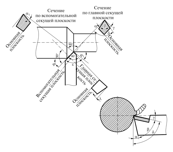
The main cutting tool for turning centres are picks. A tool consists of a body and a head (cutting part) (fig. 2.3). Three surfaces (facets) are produced on the pick head by grinding: the front surface is where the chip comes off during cutting, the back surfaces. the main and auxiliary. face the workpiece. The main work in the cutting process is performed by the main cutting edge, which is formed by the intersection of the front and main back surfaces. The auxiliary cutting edge is formed by the intersection of the auxiliary and back surfaces. Top of cutter. the place where main and auxiliary cutting edges meet.
The position of the surfaces forming the cutting part of the cutter is characterised by the angles, for the definition of which the following conventional planes are introduced (Fig. 2.4); cutting plane (PM), tangent to the cutting surface in the considered point of the cutting edge; main plane (MP), parallel to the longitudinal and transverse feeds of the cutter; main secant plane (MSP), perpendicular to the projection of the main cutting edge onto the main plane.
I. machined surface; 2. cutting surface; 3. machined surface
Surface and cutting plane. Angle а is sharpened to reduce friction of the main rear surface against the cutting surface (Fig. 2.5). Value а depends on the type of the processed material. When machining soft, ductile materials a is greater than when machining brittle materials. The value of a normally lies between 6° and 12°. Increasing the angle a reduces the strength of the pick. Angle of acuity (3 is enclosed between the front and rear surfaces of the cutter. Angle (3) has a considerable influence on the toughness of the cutting part. As the angle increases, the toughness of the pick increases.
The cutting edge angle y is between the cutter nose and the plane perpendicular to the cutting surface, passing through the main cutting edge. The rake angle is made to facilitate the penetration of the pick into the metal, to reduce the chip friction on the cutter and to reduce its wear on the front surface. The value of the angle y depends on the mechanical properties of the material to be machined, on the material and type of cutter, on the nature of the work. With increasing mechanical properties of the machined metal the magnitude of y decreases, but the strength of the cutting part of the pick increases, because the angle of sharpening (3) increases with the decrease of y. The angle y varies between 30° and 15°. If the pick is facing downwards from the plane perpendicular to the cutting plane, the rake angle is positive, if upwards it is negative. The following relationship exists between the angles a, p, y:
The cutting angle 8 is enclosed between the cutting face and the cutting plane and is equal to the sum of the angles air.
Angles are distinguished in the main plane.
The main angle f is between the projections of the main cutting edge on the main plane and the feed direction, it affects the roughness of the machined surface. For a through cutter with sufficient rigidity of the workpiece, the angle f = 45°. The smaller f is, the better is the quality of the workpiece.
In the cutting plane, the angle of the main cutting edge is considered and measured X. The angle is between the main cutting edge and the principal plane. Angle is negative when the pick tip is highest on the main cutting edge; positive when the pick tip is lowest on the main cutting edge; equal to zero when the cutting edge is parallel to the main plane; when machining tough metal (steel, aluminium and its alloys) the angle is zero X negative, when machining hard and brittle metals (cast iron, bronze) X =0°.
Turning tools are classified according to the following criteria.
Turning tools are divided into the following main types according to their purpose.
Feeding cutters (Fig. 2.6, а, 1,2, 3) are used for machining external cylindrical and conical surfaces. These cutters are made straight (fig. 2.6, o, 1) and with a bent head (fig. 2.6, а, 2 and fig. 2.6, в), Right-handed and left-handed, which is determined by the right-handed rule (fig. 2.6, б). Turners with a bent head are also used for trimming face planes. Feedthrough cutters have the main angle in plan f = 30-60°, feedthrough thrust cutters (fig. 2.6, а, 3). Ф = 90°.
Undercutters (Fig. 2.6, а, 4) are used for machining the end planes and shoulder-angles at a right angle to the workpiece axis.
Cutting off и slotting cutters (fig. 2.6, а, 5 and 8) are used for cutting off parts and for cutting of cross grooves. Cutting cutter has two auxiliary edges located at an angle F1 = 1-2° in relation to the cross feed direction. pick head tapers to the pick base (at = 2-3°).
Fig. 2.6. Types of turning tools
Boring picks (figs. 2.6, а, 6 and 7) are used for internal cylindrical and taper surfaces. They are available in two types. for through holes (fig. 2.6, а, 6) and blind (fig. 2.6, а, 7) holes. For a boring cutter (for through holes) the angle f = 75° and the angle f = 50° X. negative.
With a boring pick, f = 95°, angle X. positive. Tapping tools are designed for tapping internal and external threads of different profiles: rectangular, triangular, trapezoidal (fig. The shape of their cutting blades corresponds to the profile and cross-sectional dimensions of the threads to be cut. In fig. 2.6, а, 9 shows a cutter for tapping a triangular external thread.
Tapping blades и profiled cutters (Fig. 2.6, а, 10 and 11) are used for machining of fillets and profiled surfaces with form lines up to 30-40 mm in length. The shape of the cutting edge of the profiled cutter corresponds to the workpiece profile.
- 2. According to shape of head: straight (fig. 2.6, а, 1 and 3), bent (fig. 2.6, а, 2, 4, 6, and Fig. 2.6, в) pulled back (Fig. 2.6, а, 8) and curved.
- 3. According to the direction of pitch: right, left (Fig. 2.6, б).
- 4. According to material: high-speed steel, carbide inserts (fig. 2.6, dd), s Ceramic metal inserts, diamond crystals.
- 5. According to their design there are cutters: solid, made of a single workpiece; compound (with inseparable connection of its parts); with soldered-on inserts, with mechanical fastening of inserts (Fig. 2.7).
Principles of turning
The technology of metal turning involves the use of special machines and cutting tools (cutters, drills, reamers, etc.).), by which a metal layer of required size is removed from the part. Turning is performed through a combination of two movements: the main one (rotation of the workpiece clamped in a chuck or faceplate) and the feed movement performed by the tool when processing parts to the specified parameters of size, shape and surface quality.
Due to the fact that there are many methods of combining these movements, the turning equipment are working with parts of different configurations, as well as carry out a list of other technological operations, which include:
- threading of various types;
- drilling, boring, reaming, reaming, countersinking;
- Cutting off parts of the workpiece;
- Grinding out grooves of different configuration on the surface of the product.
The main types of metal turning operations
Thanks to such a wide functionality of the lathe equipment, it is possible to do a lot of things. For example, it is used for machining such items as:
Naturally, turning involves obtaining a finished product that meets certain quality standards. The quality in this case refers to compliance with the requirements of the geometric dimensions and shape of the parts, as well as the degree of roughness of the surfaces and the accuracy of their relative positioning.
To ensure control over the quality of machining on lathes, measuring tools are used: at enterprises producing their products in large series. limit gauges; for conditions of single and small batch production. calipers, micrometers, nutrometers and other measuring devices.
Measuring tools often used in lathe work
The first thing to be considered when teaching turning is the technology of metal processing and the principle by which it is carried out. This principle consists in the fact that the tool, cutting its cutting edge into the surface of the product, clamps it. To remove a layer of metal corresponding to the size of this plunge, the tool needs to overcome the adhesion forces in the metal of the workpiece. As a result of this interaction, a layer of metal is removed, forming a chip. The following types of metal chips are distinguished.
These chips form when workpieces made of mild steel, copper, tin, lead and their alloys, and plastics are machined at high speeds.
Chip formation occurs when low-speed chips of low-viscosity and hard materials are machined.
Chips of this type are produced when machining workpieces made of material with low ductility.
These chips are typical of medium-speed machining of medium-hard steel and aluminum alloys.
The cutting tools of a lathe
Efficiency, which is characterized by the work on a lathe, is determined by a number of parameters: depth and speed of cutting, the value of longitudinal feed. The following conditions need to be arranged in order for the machining of the part to be of high quality:
- High rotational speed of the workpiece, which is fixed in the chuck or faceplate;
- Tool stability and sufficient influence on the workpiece;
- The maximum possible layer of metal that can be removed in a single pass;
- High stability of all machine parts and keeping them in working condition.
cutting speed is chosen based on the material properties of the workpiece, the type and quality of the tool. The spindle speed of the machine equipped with a lathe chuck or faceplate is selected in accordance with the selected cutting speed.
Different pick types are available for roughing or finishing, and the selection of the tool is mainly influenced by. Varying the geometry of the cutting part of the tool, it is possible to regulate the size of the removed metal layer. A distinction is made between right-handed cutters, which move from the tailstock to the frontstock during machining, and left-handed cutters, which move accordingly in the opposite direction.
According to the shape and location of the blade cutters are classified as follows:
Cutters are also distinguished by the purpose of use:
- undercutting (machining surfaces perpendicular to the axis of rotation);
- through (turning of flat face surfaces);
- grooving (grooving);
- shaped (producing a part with a certain profile);
- Boring (boring of holes in the workpiece);
- Tapping (tapping all types of threads);
- Cutting (cutting off a part of a given length).
Quality, accuracy and productivity of machining performed on a lathe, depends not only on the right choice of tool, but also on its geometric parameters. That is why at the lessons in special educational institutions, where future turning specialists are trained, very much attention is paid to exactly the geometry of the cutting tool.
The main geometric parameters of any cutter are the angles between its cutting edges and the direction in which the feed is carried out. Such angles of the cutting tool are called angles in plan. A distinction is made among them:
- the main angle is φ, measured between the main cutting edge of the tool and the feed direction;
- Auxiliary. φ1, respectively located between the auxiliary edge and the feed direction;
- angle at the tip of the pick. ε.
The angle at the apex depends only on how the tool is sharpened, and the auxiliary angles can also be adjusted by its setting. The increase of the rake angle reduces the angle at the apex, the portion of the cutting edge that is involved in the cutting process also reduces, and consequently the tool life also becomes less. The smaller the value of this angle, the greater the portion of the cutting edge involved in both machining and heat removal from the cutting zone. These cutters are more resistant.
Practice shows that for turning not too hard workpieces of small diameter the optimum is the main angle, the value of which is in the range of 60-90 degrees. If the treatment is necessary workpiece of large diameter, the main angle must be chosen in the range of 30-45 degrees. Auxiliary angle value depends on the pick apex strength, that’s why it does not make large (as a rule, it is chosen from the interval of 10-30 degrees).
Special attention at lessons on lathe work is also paid to how to choose the right type of cutter depending on the type of processing. So there are certain rules, according to which the machining of one or another type of surface is carried out with a pick of a certain category.
- Conventional straight and bent picks are needed for machining the outer surfaces of the part.
- Thrust picks are required for face and cylindrical surfaces. Selected for grooving and trimming workpieces.
- Boring cutters are used to process previously drilled holes.
A separate category of turning tools are cutters, with the help of which it is possible to process shaped surfaces with the length of forming line up to 40 mm. These cutters are divided into several basic types:
- by design features: rod, round and prismatic;
- According to the direction in which the product is processed: radial and tangential.
Equipment classification
Types of this equipment are subdivided on the basis of several parameters, which include:
- The maximum diameter of this workpiece.
- The maximum length of the part that is allowed to be machined on this equipment.
- Machine weight.
The length of the part that is machined on this or that model depends entirely on how much distance between its centers is maintained. When considering the diameter of the workpiece, which a certain type of lathe allows to process, this parameter ranges from 100 to 4 thousand. millimeters. It is also necessary to take into account the fact that equipment models, which can process elements of the same diameter, may have different lengths of processed workpieces.
Universal lathes can have different weights. According to this parameter the equipment is divided into such categories:
- Light machines. They do not weigh more than 0.5 tons. Components 100-200 millimeters in diameter are machined on it.
- Weight of the equipment does not exceed 4 tons. Permissible diameter of machining elements is 250-500 millimeters.
- Machine weight up to 15 tons. Diameter of the elements to be machined varies from 600 to 1250 millimeters.
- Machines are heavy. They can weigh up to 400 tons. Diameter of machining elements of 1600-4000 millimeters.
Application
Universal light screw-cutting lathe is a desktop model, which is mainly used in small enterprises or in home workshops.
The most common companies with such models of equipment are:
- Plants that produce testing and measuring equipment and instruments.
- Enterprises engaged in watchmaking.
- Experimental and experimental departments of enterprises in various industrial sectors.
Enterprises in the mechanical engineering and energy industry are equipped with heavy-duty screw-cutting lathes. This equipment is also used for machining parts assemblies and elements of special mechanisms:
But medium-heavy lathes are the most common. Thanks to them, it is possible to perform finishing and semi-finishing metal-working operations and to cut a variety of threads.
The medium universal screw-cutting lathe has many advantages. These include:
- High motor power and structural rigidity, which allow you to perform a variety of work with workpieces made of metal and other types of material.
- Wide range of spindle speeds and tool feeds.
In addition, this equipment is equipped with a variety of fixtures and mechanisms that:
- Make the work of the operating personnel safer and more comfortable.
- Enables to machine workpieces with higher precision.
- Greatly expanded functionality.
Such elements of additional equipment allow on screw-turning equipment to automate many processes of element machining.
It is also worth mentioning numerically controlled turning and screw-cutting equipment. In Soviet times, it was simultaneously produced by several companies. As a rule, enterprises producing a wide range of low-volume series products were equipped with such devices.
The design of this type of equipment and the possibility of quick changeover makes it indispensable when it is necessary to switch to the production of elements of a different modification in a minimum amount of time.
As a rule, the turning equipment is applied for machining of external surfaces having the cylindrical shape. In such situations, the feedthrough cutter is used as a tool. The allowance along the length of the machined element is usually 7-12 millimeters. This allowance in size is necessary so that the workpiece to be processed can be cut to the desired length and its ends can be machined.
Several tool types can be used for undercutting the end face of the workpiece:
For trimming and turning a small indentation on the part, the thrust cutter type is used.
And also with the help of universal turning equipment it is possible to cut grooves of different depths on the parts. A special grooving tool is used for this, and the procedure is carried out at low spindle speeds.
The same principle is used for trimming the finished piece. Finish the cutting process when the diameter of the bridge reaches 2-2,5 millimeters at the place of trimming. During this period the cutting process stops and the finished product is simply broken off the workpiece.